
In this blog today we are going to see what is an operational amplifier and the important topic parameters of operational amplifier.
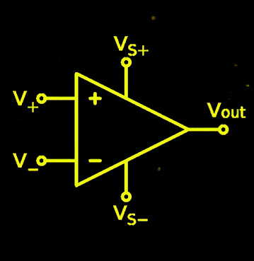
operational amplifier is a versatile device that can perform different algebraic operations like addition, subtraction, multiplication, integration, differentiation etc.
for well know this parameters of operational amplifier you can also see characteristics of ideal op-amp
parameters of operational amplifier
1. input offset voltage
firstly the voltage present on the output without any applied input is called the offset voltage.
this offset voltage is present in the operational amplifier because of transistor present in the operational amplifier is different and their voltage collector capacity is also different this difference is amplified further and this amplified voltage is the output to remove this offset voltage the opposite voltage is in input terminal this opposite input voltage is called the input offset voltage.
the value of input offset voltage is Vo = 0
lowest values are 15uV for an ideal precision op-amp and the maximum value if 6mV dc.
2. common mode rejection ratio
common mode configuration is that when we give or applied input voltage to the both of terminals of operating amplifier this stage is called the common mode rejection ratio.
and the sign for common mode is
Vcm = common mode input
V0cm = common mode output.
formula for the common mode voltage gain in Acm = V0cm / Vcm
in this common mode the output have the value 0 , Vcm =0 because same voltage in two terminals cancel the all voltage but in the practically in operational amplifier the some voltage will appear at output .
CMMR is the ratio of differential gain ad to the differential gain add to the common mode gain Acm.
CMRR = Ad / Acm
CMRR is expressed in dB ( decibles )
3. supply voltage rejection ratio
the change in the input offset voltage of operational amplifier is caused by the the variation in the supply voltage this is called supply voltage rejection ratio.
SVRR = change in input offset voltage Vio / change in the power supply V
it is also called as power supply sensitivity.
4. slew rate
slew rate is the maximum rate the can change in output per unit time. slew rate is defined as the volts per microseconds.
slew rate =difference in volts d Vo / difference in time dt
the maximum of this difference is the slew rate.
slew rate indicates that how rapidly the op-amp can change the input frequency this slew rate defines the ability of an op-amp.
5. differential input resistance
it is defined as the equivalent resistance measured with either inverting or non inverting terminal at simultaneously the other terminal is grounded that is if we measured resistance terminal the non inverting terminal is grounded.
differential input terminal is denoted by Ri
the input resistance is ideally infinite in case of op-amp
6. input capacitance
input capacitance as same as the input resistance.
it is defined as the equivalent capacitance that can be measured of either inverting or a non inverting terminal with the other terminal is grounded
the capacitance is denoted by Ci
the value for input capacitance in op-amp is ideally zero.
7. output resistance
output resistance is the measured between the output of the op-amp and the ground as the equivalent resistance
the output resistance is denoted by R0
the value of output resistance is zero.
for the op-amp 741 the value is 75 ohm
8. input offset current
input offset current is the difference between the currents into the inverting and the non-inverting currents.
the symbol for the input offset current is IIO
the formula for the input offset current is IIO = Ib+ -Ib
current into non-inverting input is Ib+
current into inverting input is Ib-
the value for the input offset current is ideally zero and practically 200nA.
9. input bias current.
input bias current is the average current flows through the inverting and non-inverting terminals of the operating amplifier.
the symbol for the input bias current is Ib.
and the formula for the input bias current is Ib = (Ib+ + Ib-)/2
the input bias current for op-amp is ideally zero.
the value is 500nA for 741 op-amp.
10. output voltage swing
output voltage swing is the difference between the positive saturation and the negative saturation voltage
and it is also defined as the output voltage range for a given ac signals.
it is V0(max)= Vsat
for supply voltage 15v voltage swing is nearly 13v.
11. output short circuit current
output short circuit current is the value of the output current that can be allowed by internal short circuit projection circuitry and the output have to shorted at the ground
output short circuit current is denoted by Isc
the typical value is 25mA
12. gain bandwidth product
when the voltage gain is a unit or 1 that bandwidth is called the gain bandwidth product.
for op-amp 741 gain bandwidth product is 1 MHz


No comments:
Post a Comment