 |
| modern earth tester |
a device is used to measure the earth resistance is called earth tester or megger earth tester.
earth tester is is essentially a direct reading ohmmeter and a hand driven generator which supplies the testing current
construction of earth tester
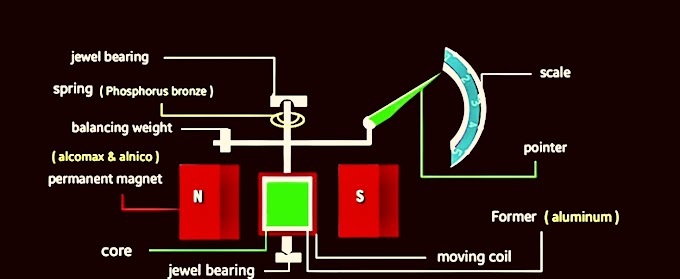
as above the earth tester is essentially direct reading ohm-meter it consists of two coils mounted at a fixed angle to each other on a common axis. the current carries by the coil is proportional to the current flowing in a circuit, when the coil carries current proportional to the potential across the resistance under test thus the potential coil acts as voltmeter while current coil acts as an ammeter. therefore the deflection of the needle shows the proportionality to the ratio of current in the two respective coils. by this the resistance shows by it directly.
 |
| construction of earth tester |
the hand operated generator produces the direct current it is necessary to flows the alternating current through the coil for eliminating the effect of electrolyte EMF,so to change the D.C. into a A.C. supply a rotary current reverser is mounted on the same shaft of the generator the alternating current in the coil will produce an alternating drops in the coil but the potential to be applied across the moving coil must be direct because the ohmmeter in a moving coil instrument works on DC alone, so for it is necessary to change the alternating drops into the direct drops for which the synchronous rotor rectifier is also attached as shown in the fig. although the instrument is immune to stray the currents, yet while taking readings sometimes it will observed that the needle vibrates it happens only in the instants when the stray A.C. has the same frequency as the frequency generated to avoid this either increase or decrease the speed of the generator.
working principal
in the earth resistance there are four terminals C1, C2, P1, P2 as shown in the fig. the C1 and P1 is connect to electrode is at ground for which we want to measure the resistance.
as shown in fig. there are two spikes P2 is shorted at spike 1st S1 and C2 is shorted with the spike S2
the distance between two spikes and electrode is 15-25
first spike is fixed between the electrode and second spike therefore the resistance is determined then this spikes taken 3 to 4m near to the earth electrode and then for the same distance near to electrode C2 and the two readings again noted the average of these three readings is the required earth resistance
you can also watch our other article of graphical recorders


No comments:
Post a Comment