in this blog today we are seeing the complete construction and working principal of energy meter
what is energy meter?
energy meter is the device which can be used to measure energy utilization to the electric load.
construction of energy meter
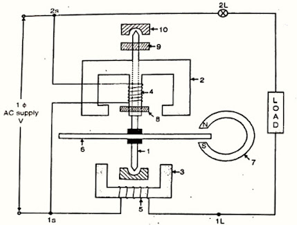
as in the fig. shows he label no. as per the sequence- spindle
- shunt magnet
- series magnet
- pressure coil
- current coil
- aluminium coil
- permanent magnet
- copper shading hand
- registering mechanism
- jewelled bearing
the construction of energy meter is divided in three systems- driving system
- controlling (breaking) system
- registering system
driving systemthere are two electromagnets made with silicon steel and laminated construction. the two magnet is known as the shunt magnet or a series magnet.
shunt magnet : the coil of shunt magnet is placed on he central limb this is known as pressure coil. shunt magnet is connected parallel with the load the pressure coil made purely inductive by placing the coil on the central limb and by providing a copper ring called as shading band
the shading band movable and can be movable along the limb to adjust the angle between the applied voltage and pressure coil current exactly 90*
series magnet :the coil placed over the series magnet is known as the current coil of the energy meter. series magnet is connected in series with load.
the current taken by the current coil is equal to the load current. the shunt magnet and the series magnet between formed air gap, an aluminium disc is placed symmetrically on the spindle. spindled rest on the jewelled bearing.on the spindle registering mechanism is fitted
aluminium is used for disc for some reasons is as follows:
- aluminium is a good conductor of heat and electricity it helps in electromagnetic induction
- eight of aluminium is less then the copper therefor it minimize the friction losses at bearing
controlling (breaking) systemit consist of c shaped permanent magnet known as breaking magnet.it is fitted on the one end of the aluminium disc for reducing the rotation of disc.
it provides the controlling torque and the value of this torque can be adjusted by shifting the position of the break magnet.
registering mechanism
it is fitted on the spindle
it consists of a pinion which engages a gear train which drives the number of plates on the dial. this is fitted near the aluminium disc because the function of the registering mechanism is to count the rotation of the aluminium disc the pointer shows the deflection as per the number of rotations this rotations are directly proportional to energy given to the load.
working principal of energy meter
when induction energy meter is connected in circuit the shunt magnet i.e. the pressure coil carries current proportional to the applied voltage across the load.
while the current coil on the series magnet carries the load current, the magnetic flux produced by there to magnets are cut by the aluminium disc.
driving torque
according to faraday's law of electromagnetic induction,EMF is induced in the disc and currents are calculated in it.
there is interaction between these currents and the magnetic field produced by the two magnets. these produce the driving force and the aluminium disc start rotating
driving torque produced is directly proportional to the flux produced by the pressure coil multiplied by the flux produced by current coil multiplied by sinα
Td = driving torque
Td ∝ Φpc.Φcc.sin
but Φpc ∝ Ipc and Φc α Icc
Td ∝ Ipc Icc sin α
but Ipc ∝ V and Icc = IL
Td ∝ V IL sinα
for finding out angle ' ' phasor diagram is plotted by taking 'v' as the reference vector
(phasor) and by considering the load as inductive load with power factor cosα lagging.
we get α = ( 90 - Φ )
Td ∝ V . IL sin (90 - Φ )
Td ∝ V . IL . cosΦ
Td ∝ P
p = V IL cosΦ
thus the driving torque is directly proportional to the power consumption of the load.
controlling torque
when driving torque is provided ,'aluminium' disc start rotating at highest speed. to control the speed, the controlling torque is provided by the break magnet.
as soon as disc start rotating flux produced by the braking magnet is cut by the disc
hence emf is induced in it. hence current are calculated in disc, they provide the controlling torque, which acts in opposite direction of driving torque and is proportional to rate of change of flux i.e. speed of aluminium disc.
where N = speed of the disc in r.p.m.
for steady speed of rotation of aluminium disc , Td = Tb
hence power is directional proportional to N
multiplying both sides by 't'.
where 't' is the time for which power is supplied to the load.
P*t ∝ N*t
therefore energy ∝ number of revolution if the disc in time 't'.
the registering mechanism is s arranged that the meter indicates 'Energy' in KWh and not the number of revolution.


No comments:
Post a Comment